Loading project Things
README.mdView source
Smart Sensor Battery Pack
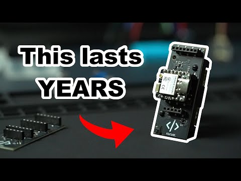
This is the experimental battery charging PCB designed for my YouTube video. You can see the full build process, design theory, and assembly in the video below:
Please note:
This board is currently missing a pull up resistor on the SCL/SDA lines - I will be adding this very soon. Software correction is possible using the XIAO pull-ups, and closing the FET early in the boot cycle. So using the board in its current form just makes the code a little more verbose.
# Force GPIO18 LOW (Turns P-Channel MOSFET on)
# Set priority such that this runs before i2c initialises
esphome:
  on_boot:
    - priority: 1200
      then:
        - lambda: |-
            gpio_config_t io_conf = {};
            io_conf.pin_bit_mask = (1ULL<<18);
            io_conf.mode = GPIO_MODE_OUTPUT;
            io_conf.pull_up_en = GPIO_PULLUP_DISABLE;
            io_conf.pull_down_en = GPIO_PULLDOWN_DISABLE;
            io_conf.intr_type = GPIO_INTR_DISABLE;
            gpio_config(&io_conf);
            gpio_set_level(GPIO_NUM_18, 0);

# Software accessible pullups
i2c:
  sda_pullup_enabled: true
  scl_pullup_enabled: true
⚠️ Safety Warning
This board involves Lithium-Ion battery charging.
- This is an experimental prototype from a hobbyist. I am not a professional engineer. It has not been certified by safety agencies (UL, CE, etc.).
- Lithium batteries can be dangerous if mishandled (risk of thermal runaway, fire, explosion, and serious injury).
- DO NOT leave this device unattended with a battery connected
- By using these files, you agree that you are solely responsible for verifying the safety of the circuit.
License & Liability
1. Non-Commercial Use Only
This project is shared under the Creative Commons Attribution-NonCommercial-ShareAlike 4.0 International license.
- You are free to: Download, modify, and build this for personal use or learning.
- You may NOT: Sell this board, use it in a product you sell, or use these files for any commercial purpose.
- If you modify and share this design, you must share it under this same license.
2. No Liability (Disclaimer)
These files are provided "As Is" for educational purposes ONLY. I am sharing my personal project notes. I accept no liability for any damage, injury, or loss that occurs from the use or assembly of these files. Use them at your own risk.